
TM 5-3805-294-23-4
0580
INSTALLATION - Continued
6.
Tighten two screws (Figure 8, Item 13) to 35 lb-ft (47 Nm).
7.
Install seat stop (Figure 8, Item 12) to seat stand (Figure 8, Item 6) with two bolts (Figure 8, Item 10) and
washers (Figure 8, Item 11).
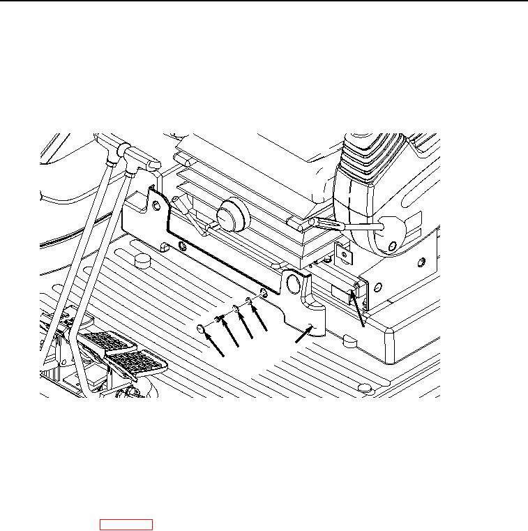
8.
Install cover (Figure 9, Item 2) to seat stand (Figure 9, Item 6) with three screws (Figure 9, Item 3), lockwashers
(Figure 9, Item 4), and washers (Figure 9, Item 5).
6
5
4
2
3
1
HYEX00832
Figure 9.
Cap and Cover Removal.
9.
Install three caps (Figure 9, Item 1) to cover (Figure 9, Item 2).
END OF TASK
FOLLOW-ON MAINTENANCE
1.
Install seat belt. (WP 0579)
2.
Perform the Standard Follow-On Maintenance Instructions. (Volume 3, WP 0384)
END OF TASK
END OF WORK PACKAGE