
TM 5-2420-230-24-1
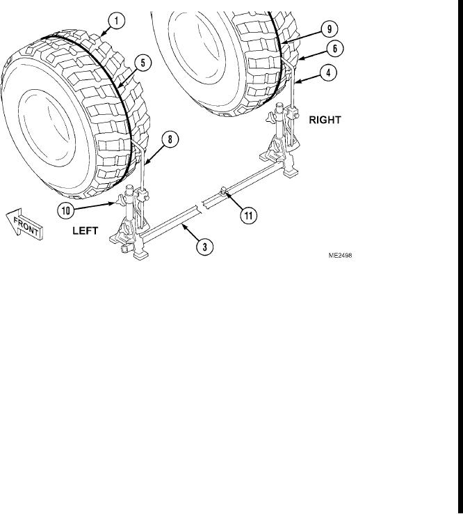
(13) Position toe gauge (3) behind front wheel and tire assemblies.
(14) Adjust fixed pointer (4) and adjustable pointer (8) to spindle height.
(15) Align fixed pointer (4) with center of scribe mark on right wheel and tire assembly (6) tire tread, and hold in that
position.
(16) Set adjustable pointer (8) to "0" with thumbscrew (10).
(17) Loosen thumbscrew (11) on toe gauge (3).
(18) Position adjustable end of toe gauge (3) behind left wheel and tire assembly (1) and align adjustable pointer (8)
with center of scribe mark (5) on tire tread. Hold adjustable pointer in that position.
(19) Verify that adjustable pointer (8) is aligned with center of scribe mark (5) on left wheel and tire assembly (1).
(20) Verify that fixed pointer (4) is aligned with center of scribe mark (9) on right wheel and tire assembly (6).
(21) Tighten thumbscrew (11) on toe gauge (3).
Change 1
5-39