
TM 5-2420-230-24-1
b. Removal.
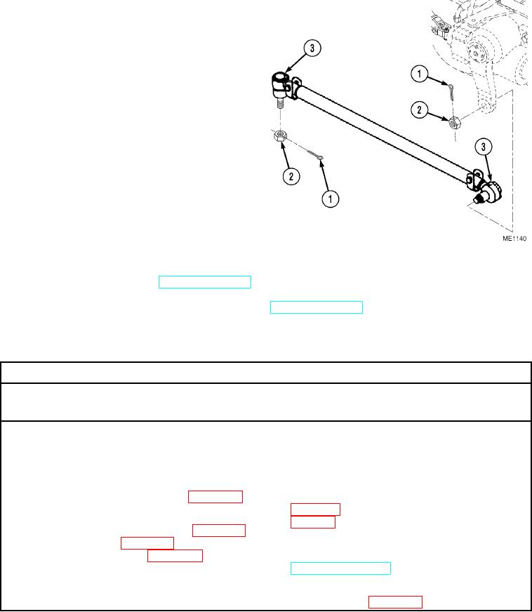
NOTE
It may be necessary to use a ball joint splitter to break the drag links.
(1)
Remove cotter pins (1) and nuts (2) from
drag links (3). Discard cotter pins.
(2)
Remove drag links (3).
c. Installation.
Installation of the drag linkages is a reversal of the
removal procedure with attention given to the
following points:
NOTE
Measurement of old drag link must be same
as new drag link.
(1)
Ensure nuts (2) are tightened.
(2)
Ensure new cotter pins (1) are installed.
d. Follow-On Maintenance.
(1)
Lube drag link ball joints (TM 5-2420-230-10).
(2)
Remove "Do Not Operate" tag from ignition switch (TM 5-2420-230-10).
END OF TASK
5-16. STEERING MITER BOX REPLACEMENT.
This Task Covers:
a. Removal
b. Installation
c. Follow-On Maintenance
INITIAL SETUP
Test Equipment
References
None
None
Tools and Special Tools
Equipment Conditions
Tool kit, general mechanics, Item 38, Appendix B
TM or Para
Condition Description
Nose cone removed.
Materials/Parts
Steering shaft disconnected from
Grease, automotive, artillery, Item 30, Appendix C
miter box.
Loctite 243, Item 20, Appendix C
Nut, self-locking, Item 122, Appendix D (3)
Drawings Required
TM 5-2420-230-24P Figure 109
Personnel Required
MOS 62B, Construction Equipment Repairer
Estimated Time to Complete Task
Refer to MAC in Appendix B
Change 1