
TM 5-2420-230-24-1
NOTE
Measure distance between the carrier bearing and the closest steering shaft yoke. Ensure the distance
is the same on both steering shafts.
(4)
Install two bolts (9), four washers (10), two new self-locking nuts (11) and carrier bearing (12). Tighten bolts to
98 lbf/ft (133 Nm).
(5)
Compress slip joint (7) and install U-joint (6) on steering column shaft (8).
NOTE
Ensure half-moon groove is aligned with bolt hole on U-joint clamps.
(6)
Install bolt (3), two washers (4), and new self-locking nut (5) on U-joint (6). Tighten bolt to 98 lbf/ft (133 Nm).
(7)
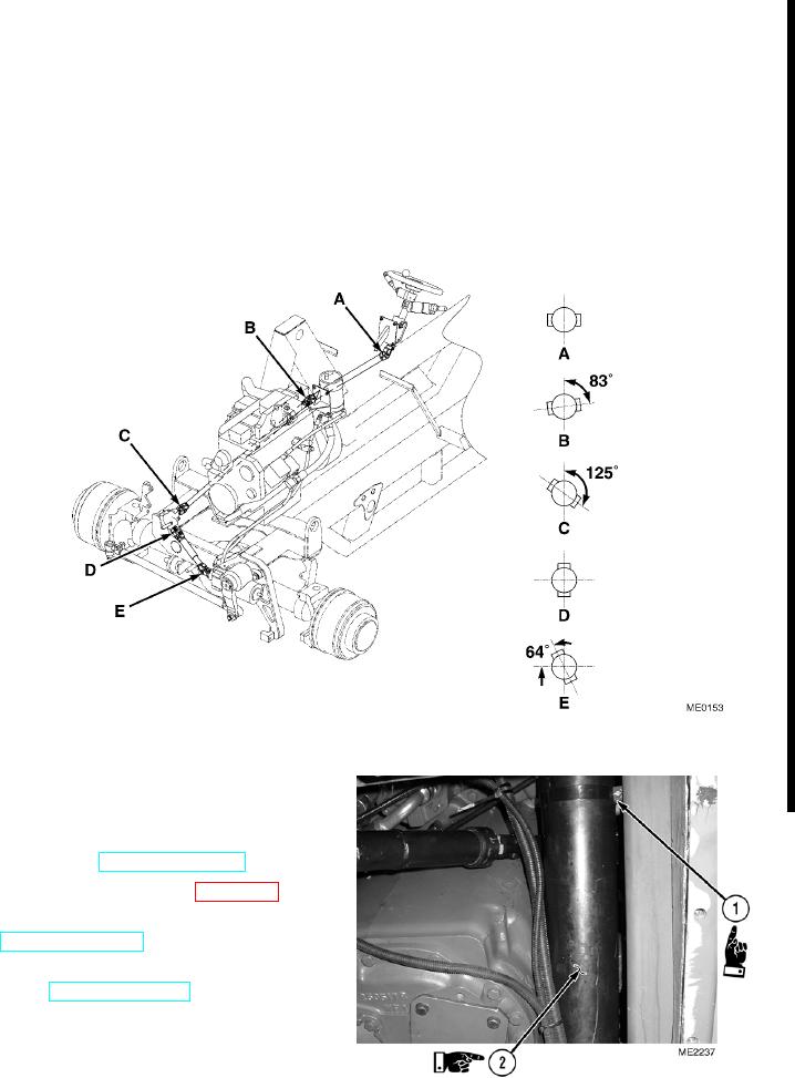
Ensure U-joints are precisely aligned. It is important that alignment is maintained during maintenance. If U-joint
alignment is not correct, remove shaft and repeat Steps (2) through (6).
(8)
Install air cleaner pipe (2) on vehicle and
tighten four clamps (1).
g. Follow-On Maintenance.
(1)
Install firewall (TM 5-2420-230-10).
(2)
Install nose cone, if removed (Para 13-18).
(3)
Remove maintenance arm and lower FEL
(4)
Remove "Do Not Operate" tag from ignition
switch (TM 5-2420-230-10).
END OF TASK
Change 1
5-33