
TM 5-2420-230-24-1
5-18. STEERING DAMPER REPLACEMENT.
This Task Covers:
a. Removal
b. Installation
c. Follow-On Maintenance
INITIAL SETUP
Test Equipment
Equipment Conditions
None
TM or Para
Condition Description
Vehicle positioned on level
Tools and Special Tools
ground.
Tool kit, general mechanics, Item 38, Appendix B
Parking brake applied.
Engine shut OFF.
Materials/Parts
Nut, self-locking, Item 105, Appendix D (2)
Electrical master switch OFF.
Nut, self-locking, Item 116, Appendix D (4 if required)
"Do Not Operate" tag attached
to ignition switch.
Personnel Required
Vehicle raised (front axle only).
MOS 62B, Construction Equipment Repairer
Drawings Required
References
TM 5-2420-230-24P Figure 113
None
Estimated Time to Complete Task
Refer to MAC in Appendix B
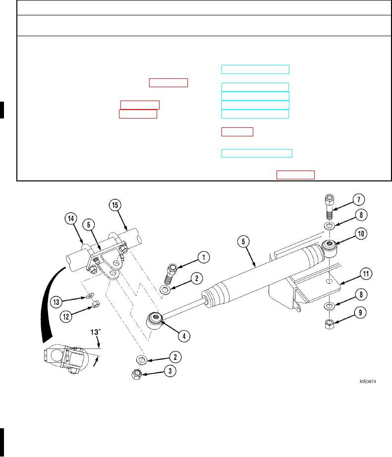
a. Removal.
(1)
Remove bolt (1), two washers (2), self-locking nut (3), crush sleeve (4) (if required), and steering damper (5) from
clamp (6). Discard self-locking nut.
(2)
Remove bolt (7), two washers (8), self-locking nut (9), crush sleeve (10) (if required), and steering damper (5)
from damper mount (11). Discard self-locking nut.
NOTE
Scribe location of U-bolts prior to removal.
(3)
If required, remove four self-locking nuts (12), four washers (13), two U-bolts (14), and clamp (6) from tie
rod (15).
Change 1