
TM 5-2420-230-24-1
b. Installation.
Remove all jewelry such as rings, dog tags, bracelets, etc. If jewelry or tools contact positive electrical
circuits, a direct short may result. Damage to equipment and injury or death to personnel may occur.
NOTE
Ensure all wires are reconnected to positions noted prior to removal.
Install cable ties as necessary.
(1)
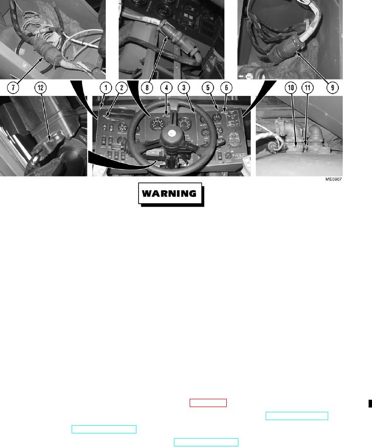
Connect electrical connector (12) to EGS.
(2)
Connect electrical connectors (11) and (10) to PDP.
(3)
Connect electrical connectors (9) to right dash panel harness.
(4)
Connect electrical connectors (8) to center dash panel harness.
(5)
Connect electrical connectors (7) to left dash panel harness.
(6)
Position right dash panel (6) and tighten down with eight screws (5).
(7)
Position center dash panel (4) and tighten down with five screws (3).
(8)
Position left dash panel (2) and tighten down with eight screws (1).
c. Follow-On Maintenance.
(0.1) Install inclinometer and bracket (center dash panel only) (Para 13-8.1).
(1)
Start engine and functionally check gauges, lights, and buzzer for proper operation (TM 5-2420-230-10).
(2)
Shut OFF engine (TM 5-2420-230-10).
(3)
Remove "Do Not Operate" tag from ignition switch (TM 5-2420-230-10).
END OF TASK
12-87
Change 1