
TM 5-3805-294-23-4
0532
REMOVAL - Continued
7.
With the aid of an assistant and rope (Figure 2, Item 12), remove four bolts (Figure 2, Item 13), lockwashers
(Figure 2, Item 14), washers (Figure 2, Item 15), and air conditioner compressor (Figure 2, Item 5) from
mounting bracket (Figure 2, Item 16). Discard lockwashers.
END OF TASK
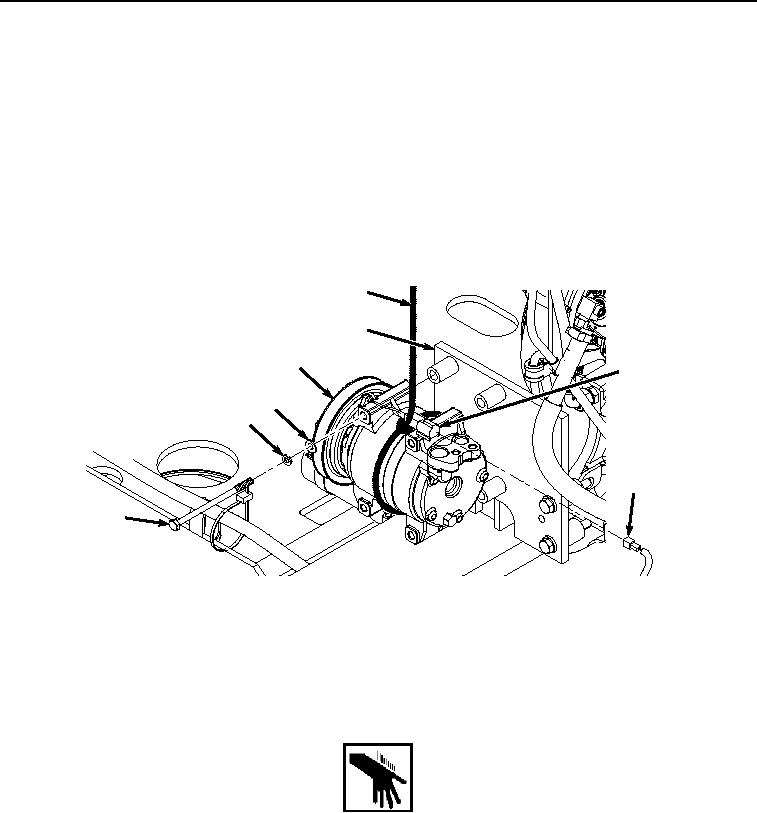
INSTALLATION
1.
With the aid of an assistant and rope (Figure 3, Item 12), install air conditioner compressor (Figure 3, Item 5)
to mounting bracket (Figure 3, Item 16) with four bolts (Figure 3, Item 13), lockwashers (Figure 3, Item 14),
and washers (Figure 3, Item 15).
12
16
5
11
15
14
10
13
HYEX00268
Figure 3.
Air Conditioner Compressor Installation.
2.
Remove rope (Figure 3, Item 12) from air conditioner compressor (Figure 3, Item 5).
3.
Install machine wiring harness W2 connector Y11 (Figure 3, Item 10) to air conditioner compressor clutch
connector (Figure 3, Item 11).
WARNING
4.
Lightly lubricate O-ring (Figure 4, Item 9) with clean oil.