
TM 5-3805-294-23-4
0533
REMOVAL - Continued
7.
Remove hose (Figure 3, Item 3) from machine.
END OF TASK
INSTALLATION
WARNING
NOTE
Route hose as noted during removal.
Install tie wraps as noted during removal.
1.
Lightly lubricate O-ring (Figure 4, Item 16) with clean refrigerant oil.
17
15
14
16
3
HYEX00519
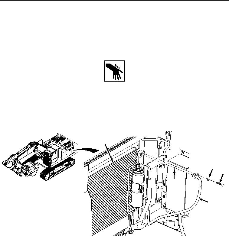
Figure 4. Hose Installation to Condenser.
2.
Install O-ring (Figure 4, Item 16) to hose (Figure 4, Item 3).
3.
Install hose (Figure 4, Item 3) with O-ring (Figure 4, Item 16) to condenser (Figure 4, Item 17) with bolt (Figure
4, Item 14) and washer (Figure 4, Item 15).
4.
Install clamp (Figure 5, Item 12) to hose (Figure 5, Item 3) and frame (Figure 5, Item 13) with bolt (Figure 5,
Item 10) and washer (Figure 5, Item 11).