
TM 5-2420-230-24-1
13-16. FRONT FENDER REPLACEMENT.
This Task Covers:
a. Removal
b. Installation
c. Follow-On Maintenance
INITIAL SETUP
Test Equipment
Equipment Conditions
None
TM or Para
Condition Description
Vehicle positioned on level
ground.
Tools and Special Tools
Tool kit, general mechanics, Item 38, Appendix B
Parking brake applied.
Engine shut OFF.
Electrical master switch OFF.
Materials/Parts
Compound, sealing, Loctite 243, Item 20, Appendix C
"Do Not Operate" tag attached
Nut, self-locking, Item 103, Appendix D (4 for left
to ignition switch.
fender; 8 for right fender)
MLC Placard removed (right
Rivet, Item 220.1, Appendix D (2)
fender only).
Washer, lock, Item 280, Appendix D (4)
Drawings Required
TM 5-2420-230-24P Figure 147
Personnel Required
MOS 62B, Construction Equipment Repairer
TM 5-2420-230-24P Figure 205
References
Estimated Time to Complete Task
None
Refer to MAC in Appendix B
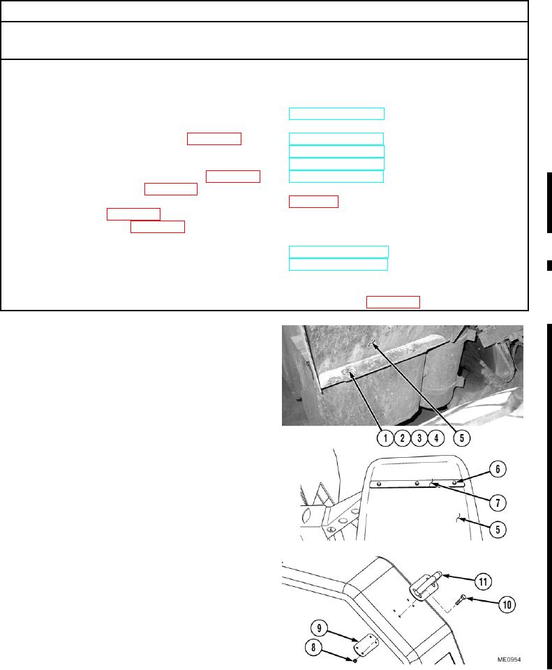
a. Removal.
NOTE
Both front fenders are removed in the same
manner. The right fender is shown.
(1)
Remove four bolts (1), washers (2), self-locking
nuts (3), and retainer plate (4) from front
fender (5). Discard self-locking nuts.
(2)
Remove three bolts (6) and hold-down strip (7)
from front fender (5).
(3)
Remove front fender (5).
NOTE
Step (4) is for the right front fender only.
(4)
If required, remove four self-locking nuts (8),
backing plate (9), and bolts (10), and grab
handle (11). Discard self-locking nuts.
Change 1
13-23