
TM 5-3805-294-23-4
0528
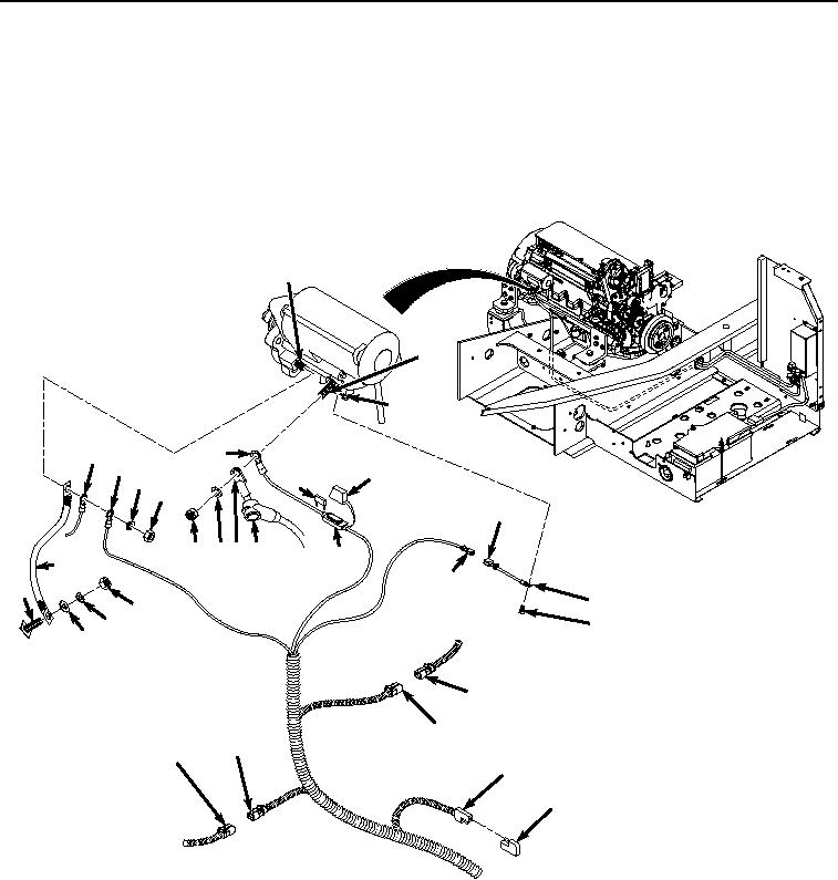
REMOVAL - Continued
NOTE
Tag and mark wires, connectors, and wiring harnesses prior to removal to ensure proper
installation.
Note position of each tie wrap and remove as required.
1.
Lift boot (Figure 1, Item 1) and slide away from starter positive cable connector (Figure 1, Item 2).
12
6
26
10
5
9
15
8
16
7
23
3 42 1
17
11
22
21
25
18
24
19
20
30
29
27
28
14
13
HYEX00518
Figure 1.
Starter Protection Wiring Harness Removal From Engine.
2.
Remove nut (Figure 1, Item 3), lockwasher (Figure 1, Item 4), starter positive cable connector (Figure 1, Item
2), and starter protection wiring harness connector (Figure 1, Item 5) from starter motor solenoid terminal
(Figure 1, Item 6). Discard lockwasher.
3.
Remove nut (Figure 1, Item 7), lockwasher (Figure 1, Item 8), starter protection wiring harness ground
connector (Figure 1, Item 9), engine interface wiring harness ground connector (Figure 1, Item 10), and ground
cable (Figure 1, Item 11) from starter motor ground terminal (Figure 1, Item 12). Discard lockwasher.
4.
Remove starter relay diode (Figure 1, Item 13) from starter protection wiring harness connector (Figure 1, Item
14).