
TM 5-3805-294-23-4
0528
INSTALLATION - Continued
8.
Install starter protection relay (Figure 3, Item 44) to panel (Figure 3, Item 40) with bolt (Figure 3, Item 42),
washer (Figure 3, Item 43), and locknut (Figure 3, Item 41).
9.
Install starter relay (Figure 3, Item 39) to panel (Figure 3, Item 40) with two bolts (Figure 3, Item 37), washers
(Figure 3, Item 38), and locknuts (Figure 3, Item 36).
10.
Install starter protection wiring harness (Figure 3, Item 34) to cover (Figure 3, Item 35) with clamp (Figure 3,
Item 33), washer (Figure 3, Item 32), and screw (Figure 3, Item 31).
11.
Connect starter protection wiring harness connector X138 (Figure 4, Item 29) to engine wiring harness
connector (Figure 4, Item 30).
12
6
26
10
5
9
15
8
16
7
23
3 42 1
17
11
22
21
25
18
24
19
20
30
29
27
28
14
13
HYEX00518
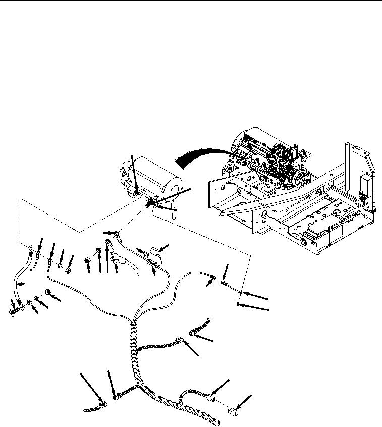
Figure 4. Starter Protection Wiring Harness Installation To Engine.
12.
Connect starter protection wiring harness connector X137 (Figure 4, Item 27) to machine wiring harness
connector (Figure 4, Item 28).
NOTE
If jumper wiring harness is removed, perform Step (11).