
TM 5-3805-294-23-4
0528
INSTALLATION - Continued
61
40
35
36
38
39
41
37
44
45
42
39
43
34
50
60
33
55
47
32
49
59
31
54
46
58
48
45
57
53
56
52
34
51
HYEX00521
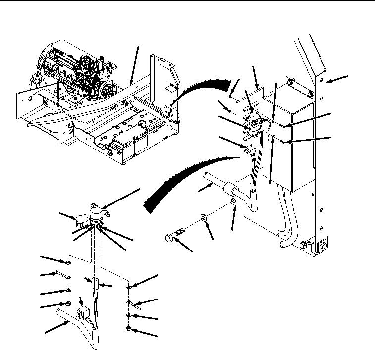
Figure 3.
Starter Protection Wiring Harness Installation To Relays.
2.
Install starter protection wiring harness connector (Figure 3, Item 58) to starter relay terminal (Figure 3, Item
60) with washer (Figure 3, Item 59), lockwasher (Figure 3, Item 57), and nut (Figure 3, Item 56).
3.
Install starter protection wiring harness connector (Figure 3, Item 53) to starter relay terminal (Figure 3, Item
55) with washer (Figure 3, Item 54), lockwasher (Figure 3, Item 52), and nut (Figure 3, Item 51).
4.
Close cover (Figure 3, Item 50) on starter relay (Figure 3, Item 39).
5.
Connect starter protection wiring harness connector (Figure 3, Item 48) to starter relay terminal (Figure 3, Item
49).
6.
Connect starter protection wiring harness connector (Figure 3, Item 46) to starter relay terminal (Figure 3, Item
47).
7.
Connect starter protection wiring harness connector (Figure 3, Item 45) to starter protection relay (Figure 3,
Item 44).