
TM 5-2420-230-24-1
20-8. FLAME SENSOR REPLACEMENT.
This Task Covers:
a. Removal
b. Installation
c. Follow-On Maintenance
INITIAL SETUP
Test Equipment
References
None
None
Tools and Special Tools
Equipment Conditions
Tool, electrical contact, Item 27.1, Appendix B
TM or Para
Condition Description
Tool, electrical contact, Item 27.2, Appendix B
Control unit removed.
Tool kit, common no. 2, Item 36, Appendix B
Tool kit, general mechanics, Item 38, Appendix B
Drawings Required
TM 5-2420-230-24P Figure 207
Materials/Parts
Tags, identification, Item 63, Appendix C
Estimated Time to Complete Task
Personnel Required
Refer to MAC in Appendix B
MOS 62B, Construction Equipment Repairer
a. Removal.
NOTE
Tag all wires and note their positions before
removal.
Note position of holder prior to removal.
(1)
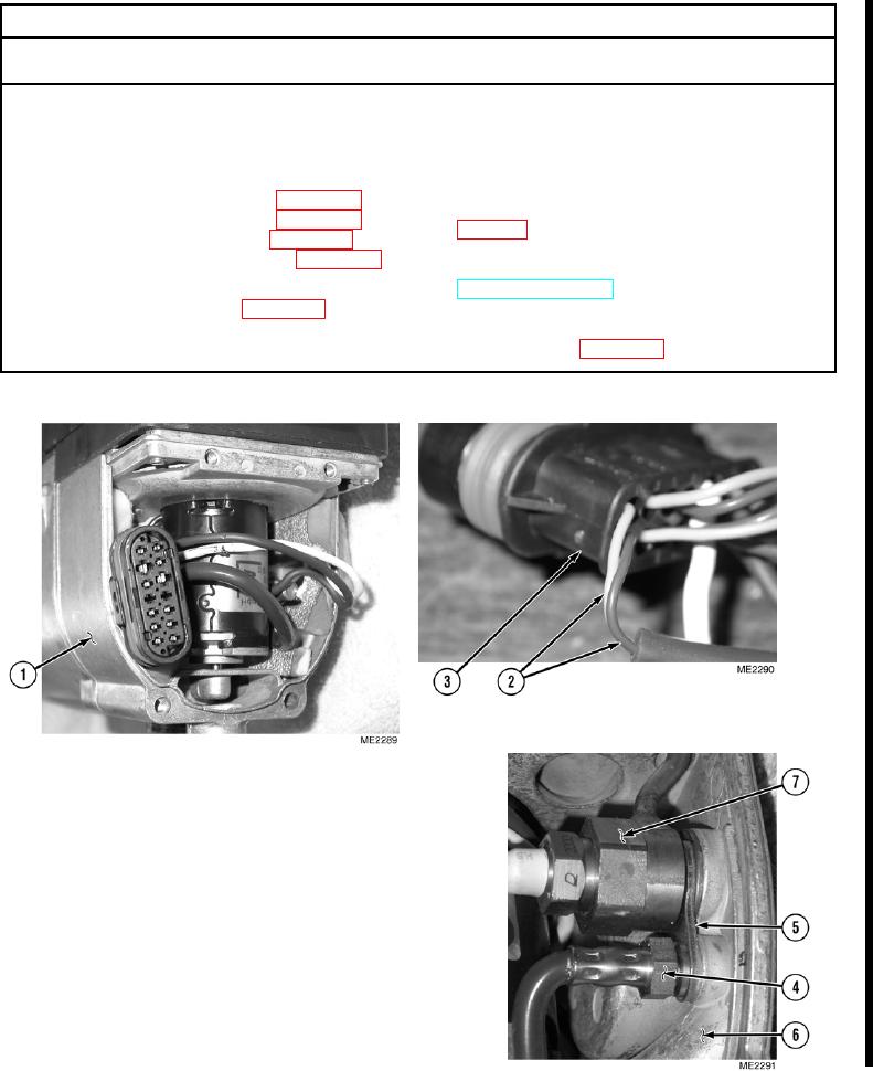
Remove exhaust cover (1).
(2)
Using an electrical contact tool, remove two
wires (2) from connector (3).
(3)
Remove flame sensor (4) from holder (5) and
air blower (6).
(4)
Remove holder (5) from glow pin (7).
Change 1